|
Orthonex Technology:
Tensile Control Rod
Introduction
to Orthonex's Tensile Control Rod for Dynamic Stabilization
Orthonex's patent pending
"Tensile Control Rod" is an innovative device for dynamic stabilization
of the spine. The Tensile Control Rod is a longitudinal implantable
device for dynamic stabilization of the spine that is attached posteriorly
to the spine in a manner similar to attachment of a conventional spinal
rod. However, unlike a conventional spinal rod, the Tensile Control
Rod allows desirable spinal movement and prevents undesirable spinal movement.
Further, the Tensile Control Rod enables adjustment of the range and dampening
of spinal motion in different directions, including the possibility of
adjustments during surgery and also non-invasively (via wireless control)
after surgery.
How
Does Orthonex's Tensile Control Rod Work?
The Tensile Control Rod includes
the following components: (1) a longitudinal sequence of incompressible
segments that connect spinal vertebrae, contain non-central longitudinal
channels, and provide spinal support; (2) substantially-inelastic members
(e.g. tensile wires) that run through these non-central channels, connect
the incompressible segments, and restrict spinal movement so that it remains
within a desirable range of motion; and (3) motion-dampening members (e.g.
springs) that also run through the non-central channels and advantageously-dampen
spinal movement within the desirable range of motion.
Figure 1 shows one example
of how Orthonex's Tensile Control Rod may be designed to provide dynamic
stabilization of the spine. The far-left portion of Figure 1 shows
the exterior of a rod-like version of this device that has been posteriorly
attached, with pedicle screws, to a sequence of spinal vertebrae.
The mid-left portion of Figure 1 shows a close-up, primarily-opaque, side
view of two of the cylindrical segments that are part of a longitudinal
sequence of multiple cylindrical segments forming the interior of the Tensile
Control Rod.
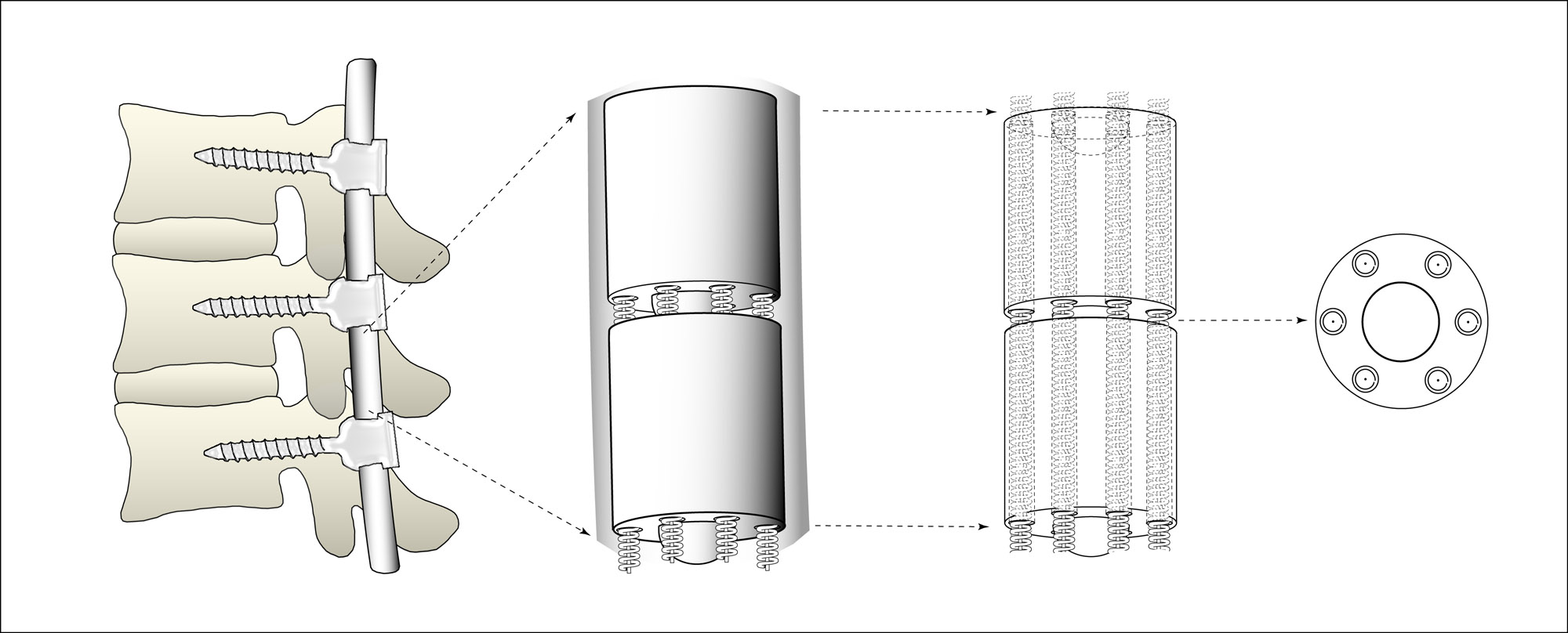
Figure 1: Orthonex's
Tensile Control Rod
(different views, before
flexion)
In the mid-left portion of
Figure 1, the upper cylindrical segment is shown with six channels that
run longitudinally through the cylinder and intersect its cross-section
in a roughly circular manner. Since the mid-left portion is
a primarily-opaque view of the segments, the channels are only visible
where they open onto the bottom end portion of the upper cylindrical segment.
Two of the six channels do not appear in this view because they are obscured
by a partial ball-like protrusion that protrudes from the bottom end portion
of the upper cylindrical segment. This ball-like protrusion fits
into a socket in the top end portion of the lower cylindrical segment.
This ball-like protrusion and socket comprise a partial ball-and-socket
joint between the upper segment and the lower segment. In this example,
within each of the longitudinal channels, there is a coaxial set of longitudinal
members including a longitudinal spring and a longitudinal wire inside
the spring. These springs and wires run longitudinally through the
upper and lower cylindrical segments and connect these segments to each
other.
The mid-right portion of
Figure 1 shows a partially-transparent side view of the same two cylindrical
segments. This portion shows interior transparent views of four of
the six longitudinal channels, each including a longitudinal spring with
a wire running longitudinally through its center. If this figure
were fully transparent, then the rear two channels would also be shown.
However, such full transparency would clutter the figure too much, so the
rear two channels are not shown. This is why this figure is called
a partially transparent, rather than a fully transparent, side view.
In this example, there is some slack in all of the connecting wires when
the spine is in a baseline configuration with minimal longitudinal extension,
tilting, and rotation. This baseline configuration is represented
by the longitudinal alignment of the two cylindrical segments. The
far-right portion of Figure 1 provides a cross-sectional view of the bottom
of the top cylinder, showing the six channels, cross-sections of the springs
with wires inside, and the ball portion of the ball-and-socket joint connecting
the two cylinders.
In this example of the Tensile
Control Rod, the rigidity of the two cylindrical segments, connected by
a partial ball-and-socket joint, resists longitudinal compression of the
spine, but allows some degree of tilting, rotation, and longitudinal extension
of the spine. The inelasticity of the connecting wires limits the
degree of tilting, rotation, and longitudinal extension to a desirable
range of motion. The force resistance of the connecting springs dampens
movement of the spine within this allowable range of motion. Acting
together, these components provide dynamic stabilization of the spine.
They advantageously allow dampened movement within a desired range of motion
and prevent movement outside this desired range of motion.
Figure 2 shows how the Tensile
Control Rod moves when the spine flexes and the cylindrical segments are
tilted relative to each other. The slack in different wires increases
or decreases when the spine tilts. When slack in a wire decreases
to zero from this tilting motion, then the wire becomes taut and prevents
further movement in that direction. This is how the substantially-inelastic
members, embodied by wires in this example, prevent undesirable movement
of spinal vertebrae relative to each other.
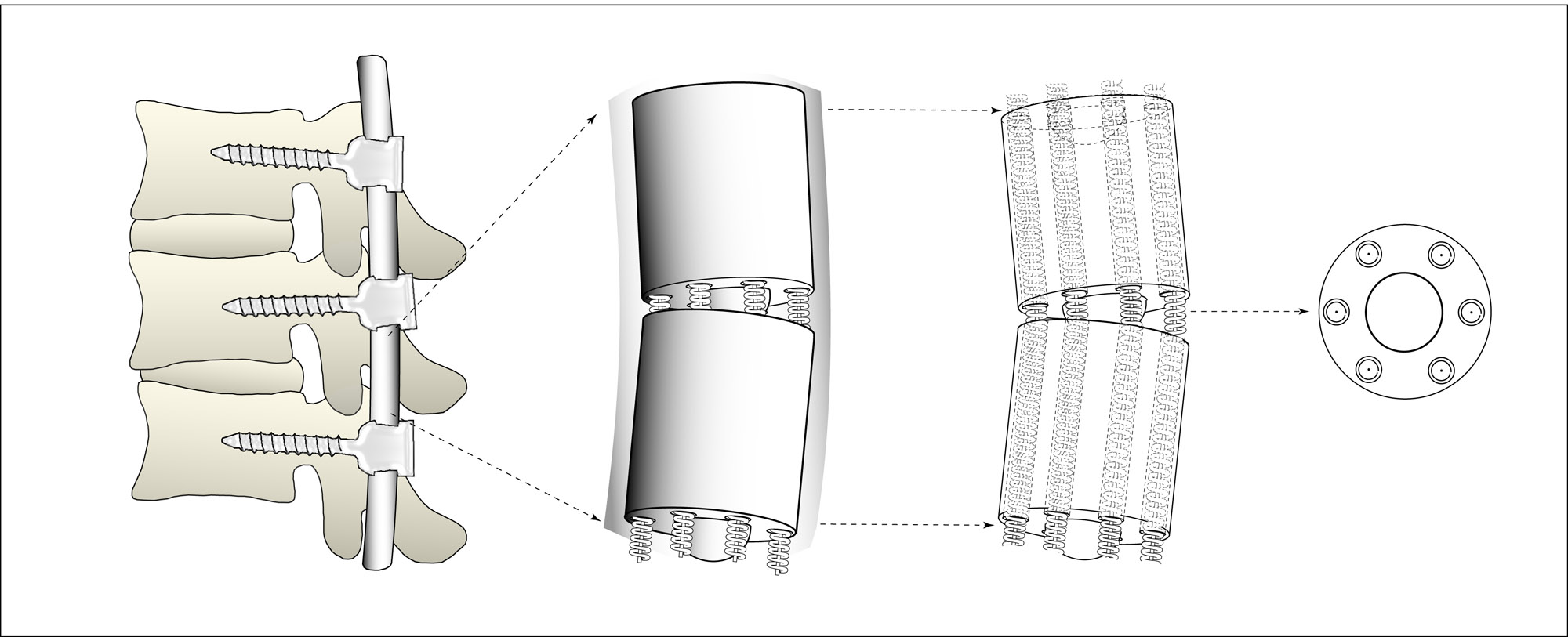
Figure 2: Orthonex's
Tensile Control Rod
(different views, after
flexion)
In Figure 2, the cylindrical
segments have been tilted relative to each other by movement of the spine.
In this example, wires on the right side of the segments have been pulled
taut by the tilting movement while wires on the left side of the segments
have become more slack. At some point, the tautness of the wires
on the right side prevents further tilting of the segments in this direction.
This is how the substantially-inelastic longitudinal members connecting
the segments, wires in this example, prevent undesirable motion of the
vertebrae relative to each other.
The tilting of the segments
in Figure 2 does not affect only the degree of slack in different wires.
This tilting also affects the extension of different springs. For
example, left-ward tilting in this example causes springs on the right
side of the segments to become more extended and the springs on the left
side of the segments to become more compressed. This is how the motion-dampening
longitudinal members, springs in this example, provide advantageous dampening
of vertebral motion within the range of motion allowed by the substantially-inelastic
members.
The relative slack or tension
of each of the tensile members (wires in this example) may be adjusted
during surgery to achieve the desired range and dampening of spinal movement.
This may include spinal distraction for gradual correction of scoliosis
or other spinal deformity. The tensile members may also be wirelessly
and non-invasively adjusted in the weeks, months, or even years after surgery
by remote communication with an implantable actuator or based on automatic
interaction between implanted sensors and the actuator. In this respect,
Orthonex's Tensile Control Rod can be one of the first "smart devices"
for dynamic stabilization of the spine, allowing non-invasive adjustment
of the range and dampening of spinal movement after surgery.
Potential
Advantages Over Current Devices and Methods for Dynamic Stabilization of
the Spine
Orthonex's Tensile Control
Rod addresses many of the limitations of current devices and methods for
dynamic stabilization of the spine.
In contrast to methods using
flexible elastic members only or flexible inelastic members only, the Tensile
Control Rod provides good support for the spinal column, provides selective
control of the degree and range of movement in different directions, and
has potential for adjustment after implantation.
In contrast to methods using
springs or spring-like cut-metal members only, the Tensile Control Rod
provides good support for the spinal column, provides selective control
of the degree or range of movement in different directions, has potential
for adjustment after implantation, and has no flexing metal springs or
spring-like structures that may weaken and break with repeated movement.
In contrast to methods using
flexible members with flexible inelastic members inside or flexible members
inside, the Tensile Control Rod provides good vertical support for the
spinal column, provides selective control of the degree or range of movement
in different directions, and has potential for adjustment after implantation.
In contrast to methods using
flexible members with rigid rods inside, the Tensile Control Rod does not
have flexing (thin) rods that may weaken or break with repeated movement,
does not require an expensive array of parts such as multiple size and
shape rigid inserts, allows natural spine movement in multiple directions
(flexion, extension, lateral bending, and torsion), and has potential for
non-invasive adjustment after implantation.
In contrast to methods using
non-contiguous rigid segments connected by flexible members, the Tensile
Control Rod: provides good vertical support for the spinal column, provides
selective control of the degree or range of movement in different directions;
and has potential for non-invasive adjustment after implantation.
In contrast to methods using
contiguous rigid segments connected by a central flexible member, the Tensile
Control Rod provides good leverage for selective control of the degree
or range of movement in different directions, allows the use rounded of
rounded (e.g. ball-and-socket) joints between rigid segments because there
is no connecting flexible member in the segment center; and has potential
for non-invasive adjustment after implantation.
In contrast to methods using
contiguous rigid segments connected by only one type of non-central flexible
member, the use of both inelastic and motion-dampening longitudinal members
(such as wires and springs) allows: firmer restriction of movement outside
the desired range of motion; and more precise control of motion-dampening
within the desired range of motion.
In contrast to methods using
telescoping members with springs or gears, the Tensile Control Rod allows
natural flexion and lateral bending movement of the spine, is less prone
to mechanical or material failure, and has the potential for non-invasive
adjustment after implantation.
In contrast to methods using
telescoping members with a flowable substance inside that are directly
attached to the vertebrae, the Tensile Control Rod provides selective control
of the degree or range of movement in different directions without weakening
the vertebrae with a large number of holes, and avoids having an irregularly-shaped
moving structure which is difficult to isolate from surrounding body tissue
and liquids.
In contrast to methods using
integrated configurations of differentially-flexible materials, the Tensile
Control Rod provides good vertical support for the spinal column, is less
prone to mechanical or material failure because there are no shearing or
large-scale flexing members, provides selective control of the degree or
range of movement in different directions, and has the potential for non-invasive
adjustment after implantation to refine therapy or accommodate patient
growth.
To summarize, Orthonex's
Tensile Control Rod has many potential advantages over current methods
of dynamic stabilization. It has considerable potential to restore
normal spinal biomechanics and offers new possibilities for adjustment
before and after implantation. It can be a useful addition to the
treatment options available for the millions of people suffering from chronic
lower back pain. |